Modeling Concepts
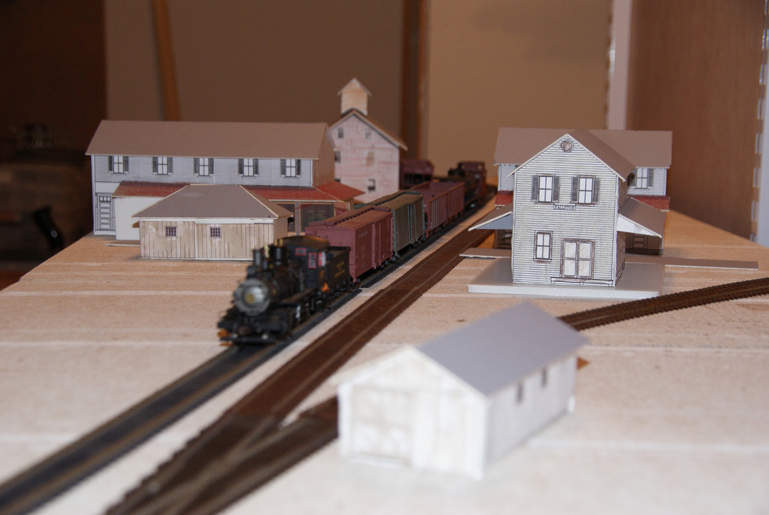
Fallston LDE, facing northbound. Track placement trial. Below at left is the same view from the Old Fallston Road bridge. The modified original 1918 M&PRR track map at Fallston, Md. These three images provide the basics from which the sequential LDEs were planned.
All prototype maps are modified from those in the Charles T. Mahan, Jr. and Rudy Fischer Collections.
All prototype maps are modified from those in the Charles T. Mahan, Jr. and Rudy Fischer Collections.
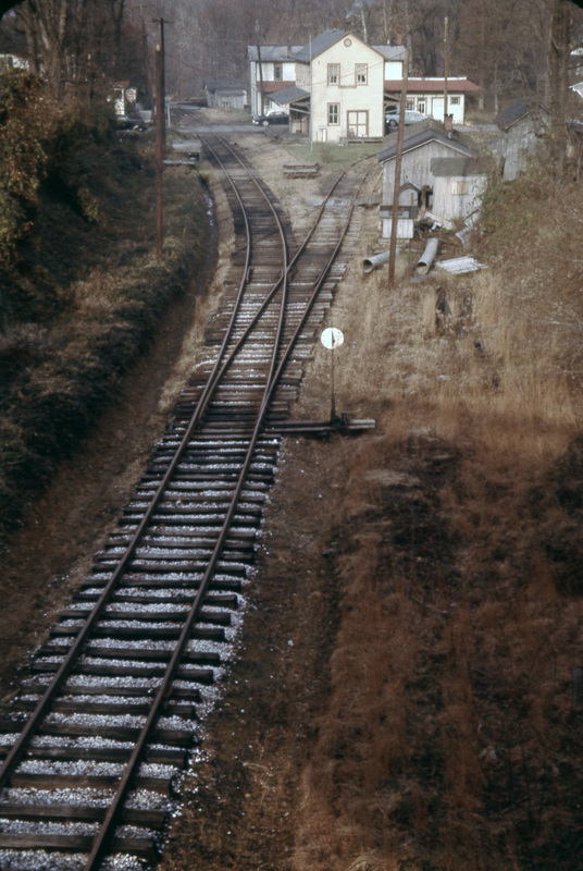
Taken from the Old Fallston Road bridge, facing northbound. Late 1957. Photograph by Holliday Obrecht, author's collection. One of the many inspirational and modelgenic photos motivating the modeling of this railroad .
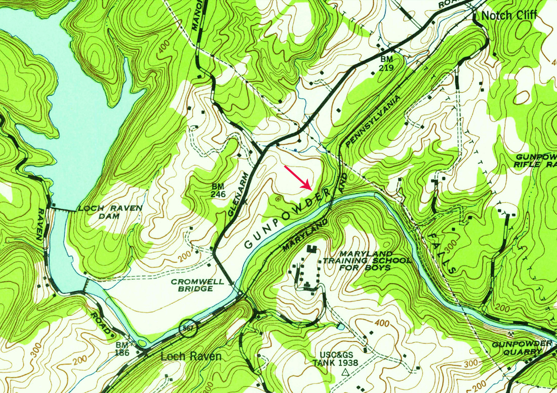
USGS Historic Topographic Map, crop. Bridge #122, Gunpowder Falls.
|
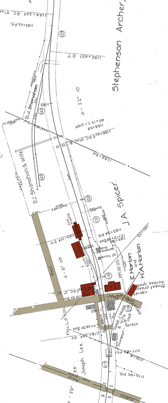
Fallston, Maryland.
Crop from original
MPRR 1918 track maps.
Author's collection. North is up.
|
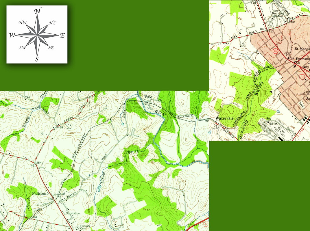
USGS Historic Topographic Map, from author's collection, merged and cropped. The modelled mainline runs from Fallston, northbound, to Vale and then Bel Air. The maps are dated 1956. The staging yards are not indicated.
Modeling Philosophy
My modeling approach has been somewhat consistent over the many years that I have been involved in the great hobby of model railroading. It has always been a prototypically - based effort coupled with liberal doses of “modeler's license” to incorporate structures, locomotives, operational practices which have not been associated with the modeled railroad but have attracted me, nonetheless. Once the lure of the Maryland & Pennsylvania RR was deeply entrenched, it enabled me to focus specifically on trying to recreate a small version of one railroad in order to “bring it to life”, albeit in a miniature sense.
Of course, as all model railroaders are acutely aware, the constraints of space, time, financial resources, and did I mention time, definitely impact the ability to bring any of the goals to fruition. So my attempts to accomplish any modeling have never really resulted in much to report. Recent downsizing to a smaller home and being granted a part of a stall in a two-car garage gave this previous weak effort some motivation.
Space
The garage space is essentially an 8 X 18 foot rectangle within a single garage stall. There needed to be access to a storage closet via a door in one corner and vertical clearance for the garage door above one end of the modeling space. I built a shelf/wall combination to form two walls of the rectangle and be able to withstand a direct nuclear strike from which the thin decks would be attached by double tracks and metal angle brackets. A recent reduction in available space has caused me to redesign the placement of the helix into the railroad space.
Which towns to model?
In spite of my desire to model every major town, a small semblance of sanity emerged to guide me to a more realistic vision. This town selection formula is based on operations potential, photogenicity, consistent railfanning views from the railroad west to east, geographic sequence along the route, a mixture of various bridge/trestle styles inherent to the Ma & Pa , and room for at least a through freight train length of single track mainline between towns. I was never happy with the engine in one town and the caboose still in the previous town concept!
Track Maps and Plans
The knowledge of the existence of tracings of original M&PRR 1918 track maps and copies of those original track maps fundamentally changed my modeling designs. This occurred in 1985, on the emergence of the Maryland & Pennsylvania RR Historical Society and the availability of the map tracings, by Society founder George Fitch. Studying the entire set reinforced my efforts to faithfully reproduce the actual track arrangements of the selected towns and portions of mainline as best as actual space and spatial arrangements would allow.
Layout Design Elements
My desire to capture the track arrangement as accurately as possible was reinforced and refined by Tony Koester, Editor of Kalmbach’s Model Railroad Planning annual magazine, with his creation of Layout Design Elements (LDE). This concept is a modeling approach in which a segment (or multiple segments tethered by connecting mainline) of a prototype railroad is reproduced so that it is visually and operationally recognizable as a miniature version of the modeled prototype. In my case the LDE segments consist of the Gunpowder Falls Bridge; the towns of Fallston, Vale, and Bel Air; and, with little resemblance to the real track maps, the connecting mainline. Even though Baltimore is planned closely as an LDE, it will likely not be treated with much scenery because of clearance issues, but function as staging (with York). It is this philosophy, with an acceptable bit of modeler’s license, that I am attempting to follow in my model Maryland & Pennsylvania Railroad.
